1 Login Interface
Open the production software on the desktop, and the running screen as shown on the right will appear. If the machine is in networking mode, you need to scan the QR code on your mobile phone to log in (as shown in the figure below). If the QR code cannot be displayed, please check the network, check whether the Internet module is connected to the Internet normally.
This machine is not a networked machine. You can use the local mode to log in. There are two accounts (as shown in the figure below) with administrators and operators. The two modes have different permissions. The administrator can enter the parameter settings and adjust the parameters, while the operator can only carry out production and cannot modify the parameters. The initial password is as follows:
Administrator: 3333
Operator: 1111
The password can be changed in the software settings

2 Production Main Interface
After logging in to the software, you will enter the main interface of the software (as shown below)
The shortcut function buttons, indicator lights, and display columns on the main interface of the system are:
Start automatic operation. It is gray when it starts; otherwise, it is green.
The offline button, offline is gray; otherwise, it is red.
The oil pump start button is gray if it is started; otherwise, it is green.
The stop button of the oil pump is brown when it is started; otherwise, it is gray.
Display which task the current production data belongs to.
Display the total number of meters for the current task.
Display how many production tasks in the cloud task have not been received.
Display the total number of meters produced today.
Show today’s hourly average output.
Display the current production speed.
Display the current position deviation from the next punching. This is the product display interface. The red part indicates that the product has been completed, the yellow part indicates that it is in production, and the black part indicates that it has not yet been produced.
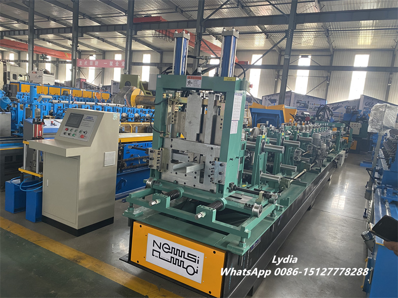
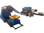
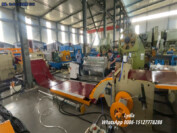
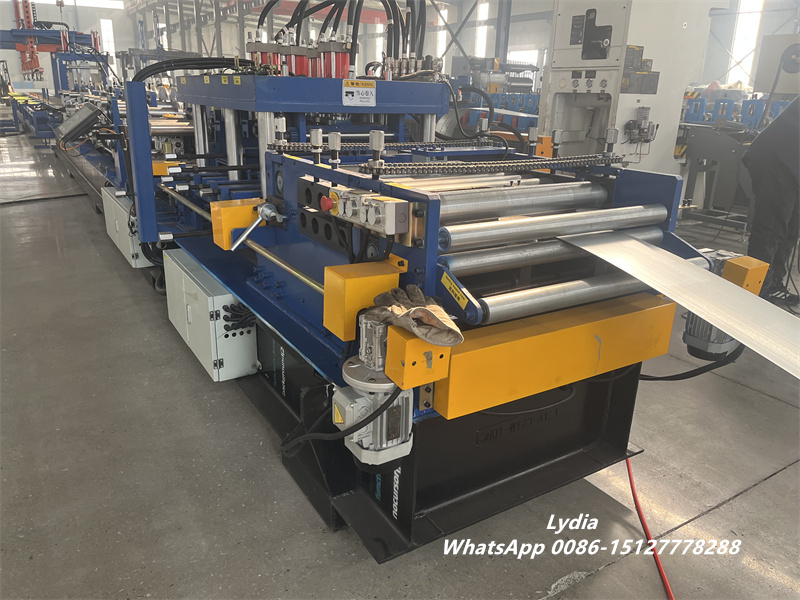
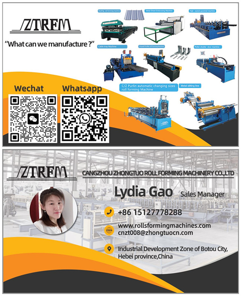
Completely automatic CZ Purlin Roll Former
3 planning interface
Click the plan column to enter the production plan interface as shown in the figure below:
“Add task”: The edit window that needs to add production tasks.
“Insert task”: Select the position to be inserted, click “Insert task” to insert a new production task, and the task cannot be inserted before the product in production.
“Delete task”: Select the production task that needs to be deleted and click to delete it.
“Clear”: Clear all tasks in the production list.
“Initialization”: Clear the current production status and restart production from the first root.
“Add product”: Select the task that needs to add a product, click “Add product” to add a new product behind the existing product.
“Insert Product”: Select the task that needs to insert the product and select the insertion position, click “Insert Product” to insert a new product.
“Delete product”: Select the product to be deleted and click.
“Quick edit”: Edit the hole position after selecting the product.
“History”: Displays products that have been produced.
This interface can edit production data. Click “Add Task” to enter the following interface.
There are three sources of production data:
The first is to remotely transfer production tasks from the mobile phone or PC to this device: click on the cloud task (as shown below).
Click to receive the task, it will show that the task has been received successfully, you can see that the task has been added to the production list, and you can see the task you just received in the unfinished (as shown below) item, after the production of this task is completed, this task will be in the unfinished interface disappear.
In the completed list, you can see that the task has been produced (as shown in the figure below). If you need to reproduce this product, click reproduce, and this product will be added to the production list again.
The second way to obtain data is to edit the data with our company’s supporting fast-transfer software and import it to the computer of this device using a USB flash drive. Click “Local Task” → “From File” to find the location of the data on the computer. Select the file to be produced (as shown below).
Click “Select” → “Add” to import the production data into the production list.
The third way to obtain production data is to edit production data under this software, click “Add Task” → “Local Task” to edit products in this interface (as shown below).
Production tasks can be edited in this interface.
Task name: refers to the production task that can be renamed, and the default name is the current time.
Quantity: Refers to how many batches of production tasks this task has.
Length: You can write the length of the first batch, and the length of other batches can be changed when editing the whole position. It must be filled in, otherwise,e an error will be reported.
Product name and suffix: can be filled in according to the first batch name of the product, or can not be filled in.
Click “Add” to complete task editing and enter the whole editing interface (as shown below):
Select the product that needs to edit the hole position, you can re-edit the product name, set quantity and product length, and then click “Quick Edit” to enter the hole position editing interface (as shown below)
For example, this machine has 6 dies and 2 cutters, 1-6 is the die, 7 is the front shear, and 8 is the post-shear. The punching position is the distance from the center of the hole to the head end. For example, the product data is
Length 3000 mm,
No. 1 100mm, 200mm
No. 2 300mm, 400mm
No. 3 700mm, 800mm
No. 4 1000mm, 1200mm
No. 5 1500mm, 1600mm
No. 6 2000mm, 2200mm
The data input method is absolute, the hole data is the distance from the center of the hole to the head end, the position of the cutter is automatically written to the corresponding shear according to the selection of pre-shearing or post-shearing, no need to edit the data, the hole position input data is as follows:
The input method is relative; the position of the cutter is automatically written to the corresponding cutter according to the selection of pre-shearing or rear shearing, no need to edit the data, the input data of the hole position is as follows.
Note: In the relative input mode, a column can only have one value, and the position of the input hole is relative to the distance from the previous hole, not the distance to the head end.
4 Set Interface
Click the settings bar to enter the parameter setting interface as shown in the figure below:
“Automatic speed” refers to the speed of the motor during automatic production, which is generally set arbitrarily between 0-600, and there is a upper limit speed according to the actual model. The user cannot set more than this value. Exceeding this value may damage the machine and affect its service life. The user can freely set the motor speed in the automatic production process according to the actual situation. For example, when producing thicker plates, the automatic speed should be appropriately reduced to prevent the motor from overloading and alarming. Similarly, when producing thin plates, the servo speed can be increased appropriately. In the process of automatic production, the automatic speed cannot be set. If the speed needs to be adjusted during automatic production, the machine needs to be paused first, and then the automatic speed can be adjusted.
“Manual speed” refers to the jog speed of the motor when the forward and reverse rotation is pressed in manual mode. The user can also freely set it between 0-600 according to the actual situation, and the use mechanism is the same as above.
Allowable error range for length and hole position accuracy.
The installation location of the printer.
Can use the printer to print manufacturer information.
Change the printer font size.
Calculate the perimeter of the current length-counting encoder. The setting of the encoder perimeter determines the accuracy of the product length. At present, the default theoretical value of the encoder perimeter of our CZ machine is 400. However, if the encoder perimeter is set to the theoretical value of 400, the actual length of the product produced may not be accurate. So we need to adjust the encoder circumference according to the theoretical length and actual length of the product. Click “”, the system will pop up the encoder perimeter automatic calculation interface as shown below:
For example, when the circumference of the encoder is 400, a board of 3000 mm is produced, which is actually 1 mm longer, then input the theoretical length of the product as 3000, and the actual length of the product as 3001, and then click “Adjust”, you can see that the encoder circumference value is automatically adjusted from 400 to 400.13. Regarding the encoder, it should be noted that since the external length measuring encoder is an important part of the fully closed-loop system, it is responsible for measuring the length of the product. Therefore, in the process of automatic production, it is necessary to ensure that the encoder is synchronized with the product, and the encoder roller must be pressed tightly without slipping, otherwise the length of the product will be inaccurate or even the motor will run off.
Since there will be a certain length loss when rear cutting, this loss must be calculated in the program, so a cutter thickness must be set. If the setting is wrong or not set, the product length will be inaccurate. The thickness of the rear cutter of our machine is 8mm and 6mm, respectively, and it is adjusted according to the actual thickness.
These two parameters only apply to the ordinary motor and hydraulic versions. The initial braking distance acts on the deceleration in advance when the plate has not entered the forming section and is positioned to 10mm (adjustable parameters). After entering the forming section, use the brake distance to locate at 8.5mm (adjustable parameters) and then start to decelerate to ensure accuracy. The two parameters of the servo version do not work.
The animation spacing is used to set the animation spacing of the main interface. If the animation spacing is not set properly, you may not be able to see the position of the rear cutter. The default is 150.
5Factory Settings
Click the factory setting to enter the parameter setting interface as shown below:
The number of cylinders refers to the total number of machine cylinders, including punching cylinders and cutter cylinders. For example, if the machine has 6 punching holes plus a pre-shear and a post-shear, the number of cylinders should be set to 8. Note that in some cases, two side-by-side cylinders on machine that always punch simultaneously should be counted as one cylinder.
Do you need a virtual keyboard when editing? If there is no external keyboard, you need to add a virtual keyboard. The default selection is yes, and the keyboard will automatically pop up when you edit (as shown below).
The maximum number of holes supported by a single product can be adjusted, and the default is 50.
Number of cutters: It is used to select the number of cutters for the machine. If the device is a single rear cutter, select “single cutter”, if the device is a front cutter plus a rear cutter, select “double cutters” to choose the front cutter or back cutter.
The cutter stop mode is only applied to the cutter after it is used.
The stop mode of the front cutter is that when all the products are produced, the plate stops at the position of the pre-shear, and there are still uncut products in the machine, and then the front cutter is used to cut the plate manually, and the mechanical clutch is pulled up. Then, manually remove the products that have not come out of the machine. It is necessary to manually measure the position of the cutter, and cut it after manual use.
The rear cutter stop means that when all the products are produced, the plate will pause at the position of the front cutter, and the customer can click to start again, and the machine will automatically cut the uncut part of the machine.
The difference between the two methods is that the stop of the front cutter saves more material and almost produces no waste, while the stop of the rear cutter generates more waste.
If your machine is equipped with automatic changeover, select “automatic changeover” for the changeover type.
If your machine is equipped with manual changeover, select “manual changeover” for the changeover type.
If your machine does not have a changeover, select “No changeover” for the changeover type.
Fill in according to the quantity of the actual model replacement motor.
The type of automatic type change is selected according to the corresponding model. It has been set before leaving the factory. This parameter will not be modified when the type change mode remains unchanged.
Machine reminder method
Never: Unless all products are completed, the machine will not stop reminding halfway.
Each batch: Stop the reminder when a batch of products is completed.
Each piece: Stop the reminder when each piece of the product is completed.
Set according to the actual selected PLC. For the time being, only Panasonic FP-XH series PLCs and PLC brands that support the standard Modbus protocol are supported.
The communication type can support RS232 serial port, and industrial Ethernet network port, and the serial port is selected by default.
The printer only supports Yida printer temporarily, the number of nozzles can be selected according to the actual number, and the printing content can be selected according to the required printing form.
The power type is selected according to the actual situation. Servo motor is selected when servo is used, asynchronous motor is selected for ordinary motor, and oil pressure motor is selected for hydraulic motor.
Cloud task: the data source can only be cloud transmission, and the networked machine only supports cloud transmission.
Click “Password Settings” to enter the password modification interface (as shown below).
6 Communication Settings
Click “Communication Setting” to enter the communication setting interface as shown in the figure below:
The factory default serial port communication settings are as follows:
The factory default network port communication settings are as follows:
Our company’s factory machine defaults to serial port communication, and network port communication requires that the corresponding PLC has an industrial Ethernet interface.
Click “Cylinder Setting” to enter the cylinder setting interface as shown below:
In order for the machine to make accurate products, various parameters must be set, and the position of the oil cylinder is one of the important parameters that affect the accuracy of the product. The cylinder position reflects the position information of each cylinder and feeds back to the system. The system will calculate when it needs to act according to the cylinder position. The position information of the oil cylinder is debugged and filled in by our company before the machine leaves the factory. Under normal circumstances, it does not need to be changed, but sometimes it needs to be fine-tuned according to the actual situation. If the position of the oil cylinder is accidentally set, you can let the material belt enter the machine in manual mode, manually punch down all the punching holes, and cut down with the cutter, and finally let the material belt come out and measure the center of each hole. For how to measure the hole position and fill in the program, the following is the specific method:
First of all, the position of No. 1 oil cylinder is the reference position, which can be set freely in theory (but cannot be set to 0), and we generally set it to 100 by default. When the No. 1 oil cylinder is set to 100, when the material belt stops at the center of the No. 1 oil cylinder and starts automatic production, the length of the waste material cut off by the first knife is 10 cm. The second thing to do is to measure the position of the other cylinders to the No. 1 cylinder. For example, the distance from the center of No. 2 to the center of No. 1 cylinder is 200, then the position of No. 2 cylinder is 200+100=300. That is: the position of No. N oil cylinder = the distance from No. N oil cylinder to No. 1 oil cylinder + the reference position of No. 1 oil cylinder.
Click “”, (currently only supports the automatic adjustment of the rear cutter) can be used to automatically adjust the position information of the rear cutter, input the actual distance and theoretical distance from the first hole to the cutter (as shown in the figure below), click to adjust the cutter position, the program will automatically adjust the cutter position.
If the die has upper and lower limit sensors, the upper and lower limits do not need to set the delay time, the default is 0ms, if there is no corresponding sensor, you need to use the delay to simulate the original point of the limit sensor to limit the action time of the cylinder.
8 Cylinder Test
Click “Cylinder Test” to enter the cylinder test interface as shown below:
The oil cylinder test is a manual action oil cylinder, which is generally used for manual punching and cutting, or checking whether the oil cylinder is normal. The origin and moving point of the window reflect the position of the die. The light green reflected by the sensor of the machine indicates that the oil cylinder has reached its current position, and the dark green indicates that the oil cylinder has not reached its current position.
Note: When operating this interface, please pay attention to whether the machine is safe.
9 Machine Change
Click “Machine Change” to enter the change interface as shown in the figure below:
The status display of the type change. If the automatic type change is not started, it will be dark green, and it will show that the type change is preparing. And after clicking “Adjust”, it will change to dark and light green alternately, and it will show that the system is changing type.
Plate width display, the plate width can be calculated automatically after inputting the plate width thickness (current thickness), waist height (A current length), bottom width (B current length), and lip (C current length).
Choose the type change method according to your needs, and temporarily support four types of change methods: C type, Z type, and U type.
The plate thickness is based on the plate thickness selected when calibrating the benchmark, and will not be modified unless the benchmark is recalibrated.
corresponds to the height of the replacement type, B is the bottom width of the replacement type, and C is the lip.
Display the current position and target position of the corresponding motor, and you can jog to make the motor move forward and backward. You can see the positive and negative limit indicator lights of the corresponding motor. If the limit is not touched, it will be light green, and if it hits the limit, it will be dark green.
Changeover start and stop buttons
Click “Model Change Setting” to enter the parameter setting of the model change. When using the automatic model change function for the first time or when the automatic model change is inaccurate, it is necessary to perform a model change calibration. Calibration and change methods:
- Set the action mode of A1 and A2 lane change mode. Since different devices A1 and A2 operate in different ways (simultaneously, independently, and in the same direction), it is necessary to select “A1, A2 synchronous action,” or “A1, A2 independent,” or A1, A2 in the same direction. If you are not clear about the working method of machines A1 and A2, please contact us.
- Set the maximum size, click “Maximum Size Setting” under the model change interface, the maximum size of each model is inconsistent, fill in according to the actual model.
- Set the resolution of the changeover encoder. Unless it is a special model, the default resolution of our changeover encoder is 1000, no need to set.
- Set the reduction ratio of each transformation. The reduction ratio here refers to the distance that the encoder moves for one revolution, and the reduction ratio of each conversion may be different for different machines. For example, if the encoder rotates one circle, the type change of track B will advance 1mm, then the reduction ratio of track B should be set to 1. We will set the correct reduction ratio before leaving the factory. If you encounter unexpected situations such as data loss, please contact us.
- Set tolerance. The allowable deviation here refers to the deviation allowed for automatic type change, in millimeters. It is worth noting that the deviation here should not be set too small. If it is set too small, there may be a phenomenon where the type change motor cannot be positioned when it rotates back and forth. Generally, the factory default setting of the deviation here is 1.
f.Set the current value of the encoder. It is necessary to set the current value of the encoder when the machine is not debugged or when the automatic type change needs to be recalibrated. The following is the specific methods.
f1.Manually adjust the machine to change the type (C type, any specification), and the height on both sides and the width of the lip of the board shape required to be made are basically the same.
f2.Let the machine produce a product, measure and record the bottom width, height, and lip of the product (if the scale of the machine has been calibrated, you can directly read the relevant parameters from the scale).
f3.Fill in the measured A height, B bottom width, and C lip into the corresponding size column (as shown in the figure below).
After filling in all, the software will automatically calculate the target position of each type-changing motor, and the next thing to do is to set the current position parameter of the type-changing motor to be the same as the target position parameter.
f4.Click “Model Change Setting” under the model change interface, as shown in the figure below, the target position has been calculated by the program at this time, what needs to be done is to fill in the “Target Position” in the blank column of “Encoder Setting Value”, and click “setting”.
Use of automatic changeover:
After the changeover calibration is set in the previous step, you can directly select the type of changeover on the main changeover interface, fill in the specification data to be made (bottom width, height, lip), and the program will automatically calculate the target position of each motor, click “Adjustment”, the device will start automatic changeover, when it reaches the target position within the error range, the changeover will automatically stop.
10 Inkjet debugging
Click “Coding Debugging” to enter the coding debugging interface as shown in the figure below.
It can be used to check whether the printing from the upper computer to the inkjet printer is normal, edit the required content in the printing content column, and click print. If you can see the edited printing content on the inkjet printer, the communication between the upper computer and the inkjet printer is normal.
11 View Log
Click “View Log” to enter the production log recording interface as shown below:
Click “Command Log”, you can see the command record, you can view the action record of the cylinder and the inkjet code, and it is convenient to judge the fault when there is a fault, as shown in the figure below:
Click “Operation Log” to record when and by whom the production software logs in, as shown in the figure below:
12 Help Interface
Click the help column to enter the help interface as shown below:
In this interface, you can see the current version of the software, language switching (temporarily only supports switching between Chinese and English), and click “Contact Us” to view our company address, contact information, and website, which is convenient for customers to contact us as shown in the figure below.
13 Exit
Click the exit bar to exit the production software and return to the computer desktop as shown below:
14 Shutdown
Click the shutdown bar to shut down the production computer as shown below:
Punching and shearing
- Pre-production Inspection
Trial punching and cutting in the state of no material, check whether the falling and lifting positions of the punch are normal, check whether the moving parts of the limit switch are loose, check whether there is interference in the circuit and oil circuit.
- Trial Punching
Use a piece of leftover material (the thickest board thickness required) to try punching. If there is any abnormality, please check the pressure. Use a small round rod with a diameter of less than 5 to withstand the coil end of the relief valve, and observe the highest value of the pressure gauge. Generally, it should be 1 0- 12 kg/cm2. If the pressure is not reached, please adjust it by adjusting the pressure regulating valve superimposed on the overflow valve. When adjusting, turn the handle to observe the pressure change until it reaches the normal value. Before entering the punching die, adjust the punching die position. Drive slowly into the ditch to see if there is any interference.
- Trial Shearing
Run the scissors on the upper and lower empty plates, check whether the moving parts of the travel switch are loose, whether there is interference in the circuit, and the oil circuit. Slowly drive into the knife edge. If there is any interference, adjust the position of the knife edge in time, after passing through the knife edge smoothly, observe the gap between the plate and the knife edge, generally about 1-2mm, open about 100mm, and try to cut. Observe whether the incision is smooth or not, and if necessary, adjust the gap between the knife edges and try cutting again until it is smooth and free of burrs. The manual plate passes through the knife again, and observes whether the plate collides with the knife. If necessary, adjust the front knife group and the rear knife group dislocation gap.
- Production
After the above steps are correct, the production shall be carried out referring to the manual of the electrical part. The first sample produced shall be measured for the first piece, and mass production can only be started after confirming that it is correct. (It is necessary to observe whether there is any abnormality in the moving parts of the whole machine during the production process, and measure whether the effective length of the product is qualified from time to time.)

The ZTRFM heavy-duty coil recoiler is engineered for handling narrow-width and light-gauge strip materials, ensuring
The metal coil slitting and recoiling machine is designed for processing narrow-width strips with high

Zhongtuo Roll Forming Machinery Partners with Lange Steel Network to Launch a New Era of
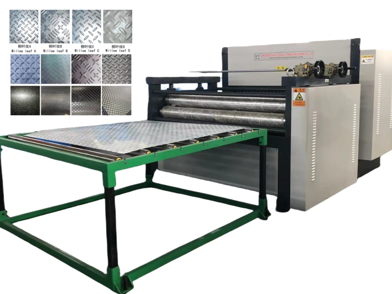
High-Precision Coil Embossing Machine for Decorative and Structural Metal Applications As a trusted coil embossing
STAY IN THE LOOP